Ground Effect
For certain flight conditions or types of aircraft, incorporating ground effect may be important. Mathematically, the ground effect is simply an extra boundary condition imposed such that the velocities normal to the ground plane are zero. In vortex lattice methods, this is accomplished by mirroring a second copy of the mesh across the ground plane such that the vortex induced velocities cancel out at the ground. Some VLM solvers, such as AVL, model ground effect by mirroring across an x-y plane. This is simple to implement but is not strictly correct because of the influence of the angle of attack.
In OpenAeroStruct, the ground effect mirroring plane is parallel to the freestream (influenced by angle of attack). This means that configurations deep in ground effect (small altitude compared to wingspan) or at higher angles of attack will obtain the correct ground effect correction.

To enable ground effect, add a groundplane: True attribute to your aerosurfaces, like so:
import numpy as np

import openmdao.api as om

from openaerostruct.meshing.mesh_generator import generate_mesh
from openaerostruct.geometry.geometry_group import Geometry
from openaerostruct.aerodynamics.aero_groups import AeroPoint

from openmdao.utils.assert_utils import assert_near_equal, assert_check_totals

# Create a dictionary to store options about the mesh
mesh_dict = {"num_y": 7, "num_x": 2, "wing_type": "CRM", "symmetry": True, "num_twist_cp": 5}

# Generate the aerodynamic mesh based on the previous dictionary
mesh, twist_cp = generate_mesh(mesh_dict)

# Create a dictionary with info and options about the aerodynamic
# lifting surface
surface = {
    # Wing definition
    "name": "wing",  # name of the surface
    "symmetry": True,  # if true, model one half of wing
    # reflected across the plane y = 0
    "groundplane": True,
    "S_ref_type": "wetted",  # how we compute the wing area,
    # can be 'wetted' or 'projected'
    "fem_model_type": "tube",
    "twist_cp": twist_cp,
    "mesh": mesh,
    # Aerodynamic performance of the lifting surface at
    # an angle of attack of 0 (alpha=0).
    # These CL0 and CD0 values are added to the CL and CD
    # obtained from aerodynamic analysis of the surface to get
    # the total CL and CD.
    # These CL0 and CD0 values do not vary wrt alpha.
    "CL0": 0.0,  # CL of the surface at alpha=0
    "CD0": 0.015,  # CD of the surface at alpha=0
    # Airfoil properties for viscous drag calculation
    "k_lam": 0.05,  # percentage of chord with laminar
    # flow, used for viscous drag
    "t_over_c_cp": np.array([0.15]),  # thickness over chord ratio (NACA0015)
    "c_max_t": 0.303,  # chordwise location of maximum (NACA0015)
    # thickness
    "with_viscous": True,  # if true, compute viscous drag
    "with_wave": False,  # if true, compute wave drag
}

# Create the OpenMDAO problem
prob = om.Problem()

# Create an independent variable component that will supply the flow
# conditions to the problem.
indep_var_comp = om.IndepVarComp()
indep_var_comp.add_output("v", val=248.136, units="m/s")
indep_var_comp.add_output("alpha", val=5.0, units="deg")
indep_var_comp.add_output("Mach_number", val=0.84)
indep_var_comp.add_output("re", val=1.0e6, units="1/m")
indep_var_comp.add_output("rho", val=0.38, units="kg/m**3")
indep_var_comp.add_output("cg", val=np.zeros((3)), units="m")
indep_var_comp.add_output("height_agl", val=8000.0, units="m")

# Add this IndepVarComp to the problem model
prob.model.add_subsystem("prob_vars", indep_var_comp, promotes=["*"])

# Create and add a group that handles the geometry for the
# aerodynamic lifting surface
geom_group = Geometry(surface=surface)
prob.model.add_subsystem(surface["name"], geom_group)

# Create the aero point group, which contains the actual aerodynamic
# analyses
aero_group = AeroPoint(surfaces=[surface])
point_name = "aero_point_0"
prob.model.add_subsystem(
    point_name, aero_group, promotes_inputs=["v", "alpha", "Mach_number", "re", "rho", "cg", "height_agl"]
)

name = surface["name"]

# Connect the mesh from the geometry component to the analysis point
prob.model.connect(name + ".mesh", point_name + "." + name + ".def_mesh")

# Perform the connections with the modified names within the
# 'aero_states' group.
prob.model.connect(name + ".mesh", point_name + ".aero_states." + name + "_def_mesh")

prob.model.connect(name + ".t_over_c", point_name + "." + name + "_perf." + "t_over_c")

# Import the Scipy Optimizer and set the driver of the problem to use
# it, which defaults to an SLSQP optimization method
prob.driver = om.ScipyOptimizeDriver()
prob.driver.options["tol"] = 1e-9

# Setup problem and add design variables, constraint, and objective
prob.model.add_design_var("height_agl", lower=10.0, upper=8000.0)
prob.model.add_design_var("wing.twist_cp", lower=-10.0, upper=15.0)
prob.model.add_constraint(point_name + ".wing_perf.CL", equals=0.5)
prob.model.add_objective(point_name + ".wing_perf.CD", scaler=1e4)

# Set up and run the optimization problem
prob.setup()

prob.run_driver()
If groundplane is turned on for an AeroPoint or AeroStructPoint, a new input will be created (height_agl) which represents the distance from the origin (in airplane coordinates) to the ground plane. The default value, 8000 meters, produces essentially zero ground effect.
Note that symmetry must be turned on for the ground effect correction to be used. Also, crosswind (beta) may not be used when ground effect is turned on. Finally, take care when defining geometry and run cases that your baseline mesh does not end up below the ground plane. This can occur for wings with long chord, anhedral, shear, tail surfaces located far behind the wing, high angles of attack, or some combination.
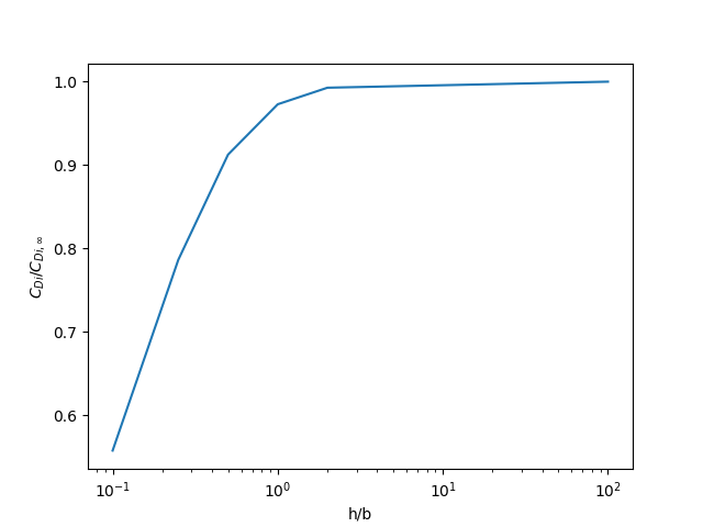
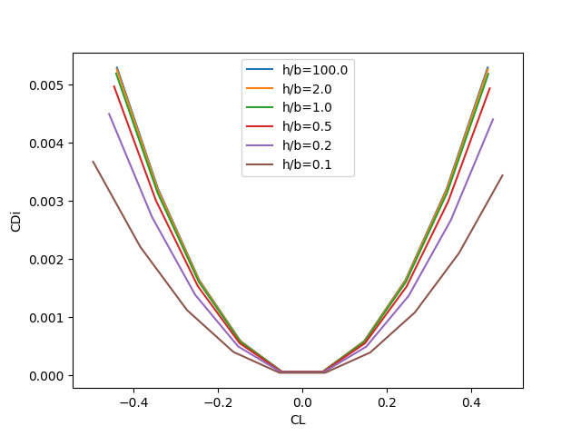
The following plots (generated using the examples/drag_polar_ground_effect.py file) illustrate the effect of the ground plane on a rectangular wing with aspect ratio 12.
As the wing approaches the ground, induced drag is significantly reduced compared to the free-flight induced drag.
These results are consistent with published values in the literature, for example “Lifting-Line Predictions for Induced Drag and Lift in Ground Effect” by Phillips and Hunsaker.